XY Table
by ReDo.Pro (@ReDo.Pro)
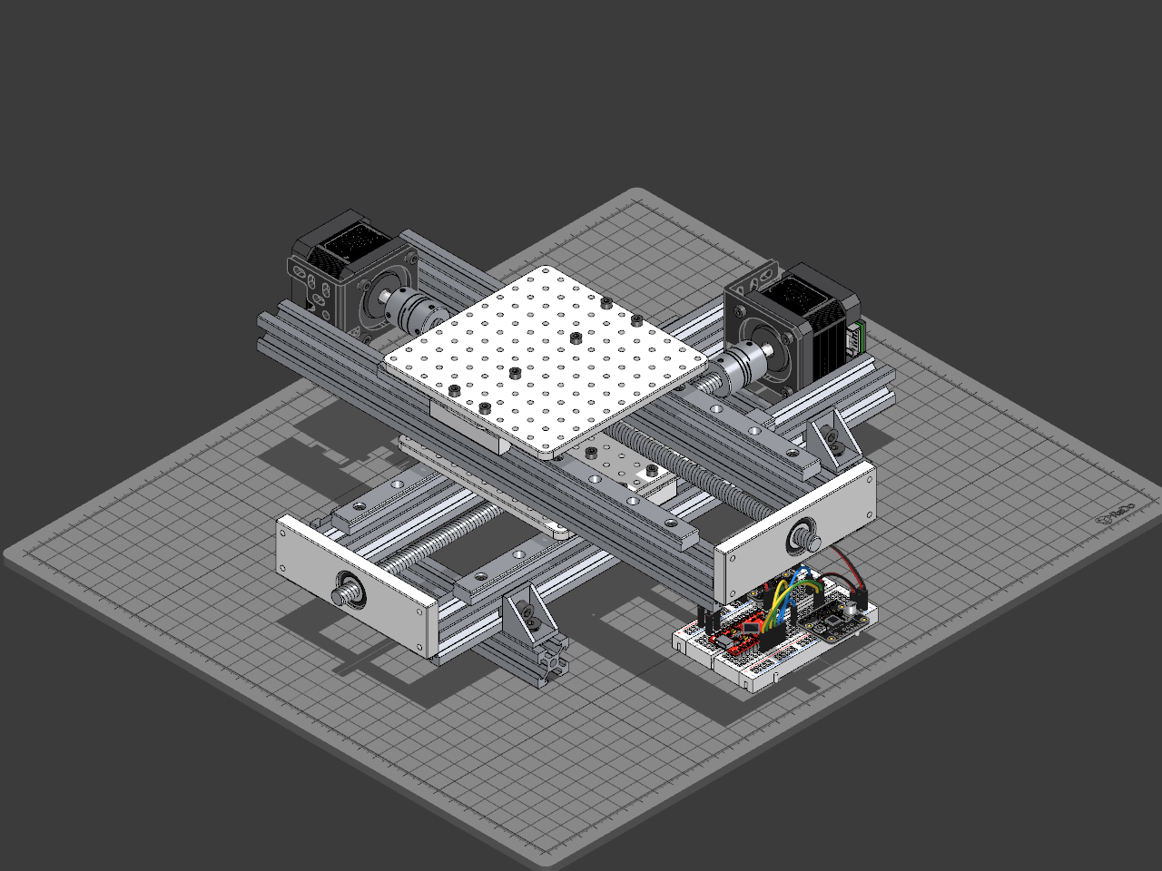
Description
A motorised XY table: two linear stages stacked crosswise, each a saddle on two MGN12 rails, driven along a T8 lead screw by a NEMA 17 stepper. Everything is off-the-shelf 2020 aluminium profile and hardware.
## How it is built
- **The frame.** Each stage runs on two 300 mm profiles. The lower one stands on two cross profiles, squared to them with corner brackets, so its motor clears the table.
- **The rails.** Each profile carries a 200 mm MGN12 rail, screwed down into V-slot T-nuts in the profile's top groove. An MGN12H carriage rides on each rail, and a 110 × 110 mm plate is screwed across the pair on 2.5 mm spacers, which lift it clear of the lead nut's flange.
- **The drive.** Two nut blocks under the plate, each on a spacer of its own, hold a flange with the lead screw's flanged T8 nut against it; the screw runs between them. At the near end a 608 bearing is pressed on the screw and turns in the end plate. At the far end a flexible coupler joins it to the motor's 5 mm shaft, its four grub screws tight on both shafts. The motor is held on an L-bracket by four screws through the bracket's slots, which let the bracket slide 1.6 mm along them to sit flush on the back profile. The lead screw runs 13 mm above the profile's groove, so one of the slots in the bracket's foot crosses the groove: an M4 screw through it bolts the foot to the profile, into a thin M4 nut in the groove.
- **The second stage.** The upper stage is the same stage turned a quarter turn, its profiles tied to the lower saddle with T-nuts. Its plate is the table.
- **The controller.** A SparkFun Pro Micro and two TMC2209 drivers share a half-size breadboard on the bench. Each driver plugs into its own 10-pin header and overhangs the breadboard's edge, so the holes beside its pins stay free for jumpers. D2 and D3 drive the X driver's STEP and DIR, D4 and D5 the Y driver's, and D6 and D7 each driver's ENABLE. The power rails carry the Pro Micro's VCC and GND to both drivers' logic supply.
## Build it
1. Square the lower stage's profiles onto the cross profiles with the corner brackets.
2. Drop T-nuts into the top grooves and screw the rails down, then slide the carriages on.
3. Screw the saddle plate to the carriages through its spacers, with the nut blocks and flange under it, each block on a spacer too.
4. Thread the lead screw through the lead nut, press the 608 bearing onto its near end and seat it in the end plate, and couple the far end to the motor.
5. Build the upper stage the same way on top of the saddle.
6. Plug the Pro Micro and the two drivers into the breadboard and run the jumpers: D2 to the X driver's STEP and D3 to its DIR, D4 and D5 to the Y driver's, D6 and D7 to their ENABLE pins, and VCC and GND through the rails to each driver's VDD and GND.
Each driver's screw terminal takes the motor supply (VMOTOR and GND, 12 to 24 V) and its motor's four coil wires (OUT1A, OUT1B, OUT2A, OUT2B); neither is drawn. The T8 lead screw has four starts at a 2 mm pitch, so one turn of the motor, 200 full steps, moves a carriage 8 mm.
Bill of materials
- 1 × X profile · back
- 1 × X rail · back
- 4 × M3 screw · X rail back
- 4 × T-nut · X rail back
- 1 × X carriage · back
- 2 × M3 screw · X carriage back
- 1 × X profile · front
- 1 × X rail · front
- 4 × M3 screw · X rail front
- 4 × T-nut · X rail front
- 1 × X carriage · front
- 2 × M3 screw · X carriage front
- 1 × X end plate
- 1 × X bearing
- 1 × X saddle plate
- 1 × X nut block · front
- 1 × X nut block · back
- 2 × M3 screw · X nut block
- 2 × M3 screw · X nut flange
- 1 × X nut flange
- 1 × X lead nut
- 1 × X motor bracket
- 1 × M4 screw · X motor bracket
- 1 × M4 nut in the slot · X motor bracket
- 1 × X motor
- 4 × M3 screw · X motor
- 1 × X coupler
- 4 × Grub screw · X coupler
- 1 × X lead screw
- 1 × Y profile · left
- 1 × Y rail · left
- 4 × M3 screw · Y rail left
- 4 × T-nut · Y rail left
- 1 × Y carriage · left
- 2 × M3 screw · Y carriage left
- 1 × Y profile · right
- 1 × Y rail · right
- 4 × M3 screw · Y rail right
- 4 × T-nut · Y rail right
- 1 × Y carriage · right
- 2 × M3 screw · Y carriage right
- 1 × Y end plate
- 1 × Y bearing
- 1 × Table plate
- 1 × Y nut block · right
- 1 × Y nut block · left
- 2 × M3 screw · Y nut block
- 2 × M3 screw · Y nut flange
- 1 × Y nut flange
- 1 × Y lead nut
- 1 × Y motor bracket
- 1 × M4 screw · Y motor bracket
- 1 × M4 nut in the slot · Y motor bracket
- 1 × Y motor
- 4 × M3 screw · Y motor
- 1 × Y coupler
- 4 × Grub screw · Y coupler
- 1 × Y lead screw
- 2 × M3 screw · Y profile left to the saddle
- 2 × T-nut · Y profile left
- 2 × M3 screw · Y profile right to the saddle
- 2 × T-nut · Y profile right
- 1 × Foot · near
- 1 × Corner bracket · back near
- 1 × T-nut · foot back near
- 1 × M5 screw · foot back near
- 1 × T-nut · X profile back near
- 1 × M5 screw · X profile back near
- 1 × Corner bracket · front near
- 1 × T-nut · foot front near
- 1 × M5 screw · foot front near
- 1 × T-nut · X profile front near
- 1 × M5 screw · X profile front near
- 1 × Foot · far
- 1 × Corner bracket · back far
- 1 × T-nut · foot back far
- 1 × M5 screw · foot back far
- 1 × T-nut · X profile back far
- 1 × M5 screw · X profile back far
- 1 × Corner bracket · front far
- 1 × T-nut · foot front far
- 1 × M5 screw · foot front far
- 1 × T-nut · X profile front far
- 1 × M5 screw · X profile front far
- 1 × Half-Size Breadboard for the controller
- 1 × Header 1x12 for the Pro Micro's D9 to TXO row
- 1 × Header 1x12 for the Pro Micro's RAW to D10 row
- 1 × SparkFun Pro Micro, the controller
- 1 × Header 1x10 for the X driver
- 1 × TMC2209 driver for the X motor
- 1 × Header 1x10 for the Y driver
- 1 × TMC2209 driver for the Y motor
- 1 × Spacer · X carriage back
- 1 × Spacer · X carriage front
- 1 × Spacer · X nut block back
- 1 × Spacer · X nut block front
- 1 × Spacer · Y carriage left
- 1 × Spacer · Y carriage right
- 1 × Spacer · Y nut block left
- 1 × Spacer · Y nut block right
Licences
- Aluminium Profile: CC-BY-SA-4.0, credit ReDo.Pro. Downloads: STEP, STL and 3MF
- Linear Guide Rail: CC-BY-SA-4.0, credit ReDo.Pro. Downloads: STEP, STL and 3MF
- Screw: CC-BY-SA-4.0, credit ReDo.Pro. Downloads: STEP, STL and 3MF
- V-Slot T-Nut: CC-BY-SA-4.0, credit ReDo.Pro. Downloads: STEP, STL and 3MF
- MGN12H Linear Guide Carriage: CC-BY-3.0, credit FreeCAD Library. Downloads: STEP, STL and 3MF
- Bearing Block: CC-BY-SA-4.0, credit ReDo.Pro. Downloads: STEP, STL and 3MF
- 608ZZ Ball Bearing: CC-BY-3.0, credit FreeCAD Library. Downloads: STEP, STL and 3MF
- Plate: CC-BY-SA-4.0, credit ReDo.Pro. Downloads: STEP, STL and 3MF
- Block: CC-BY-SA-4.0, credit ReDo.Pro. Downloads: STEP, STL and 3MF
- Lead Screw Nut: CC-BY-SA-4.0, credit ReDo.Pro. Downloads: STEP, STL and 3MF
- NEMA 17 Stepper Stamped Aluminium L-Bracket: CC-BY-SA-4.0, credit Pololu. Downloads: STEP, STL and 3MF
- Nut: CC-BY-SA-4.0, credit ReDo.Pro. Downloads: STEP, STL and 3MF
- NEMA 17 Stepper Motor 17HS4401: CC-BY-4.0, credit Generic. Downloads: STEP, STL and 3MF
- Shaft Coupler: CC-BY-SA-4.0, credit ReDo.Pro. Downloads: STEP, STL and 3MF
- Lead Screw: CC-BY-SA-4.0, credit ReDo.Pro. Downloads: STEP, STL and 3MF
- Profile Corner Bracket: CC-BY-SA-4.0, credit ReDo.Pro. Downloads: STEP, STL and 3MF
- Half-Size Breadboard: CC-BY-4.0, credit Generic. Downloads: STEP, STL and 3MF
- Header: CC-BY-SA-4.0, credit ReDo.Pro. Downloads: STEP, STL and 3MF
- SparkFun Pro Micro: CC-BY-SA-4.0, credit SparkFun. Downloads: STEP, STL and 3MF
- TMC2209 Stepper Driver: CC-BY-SA-3.0, credit Adafruit. Downloads: STEP, STL and 3MF