Bare-Minimum Arduino
by ReDo.Pro (@ReDo.Pro)
Description
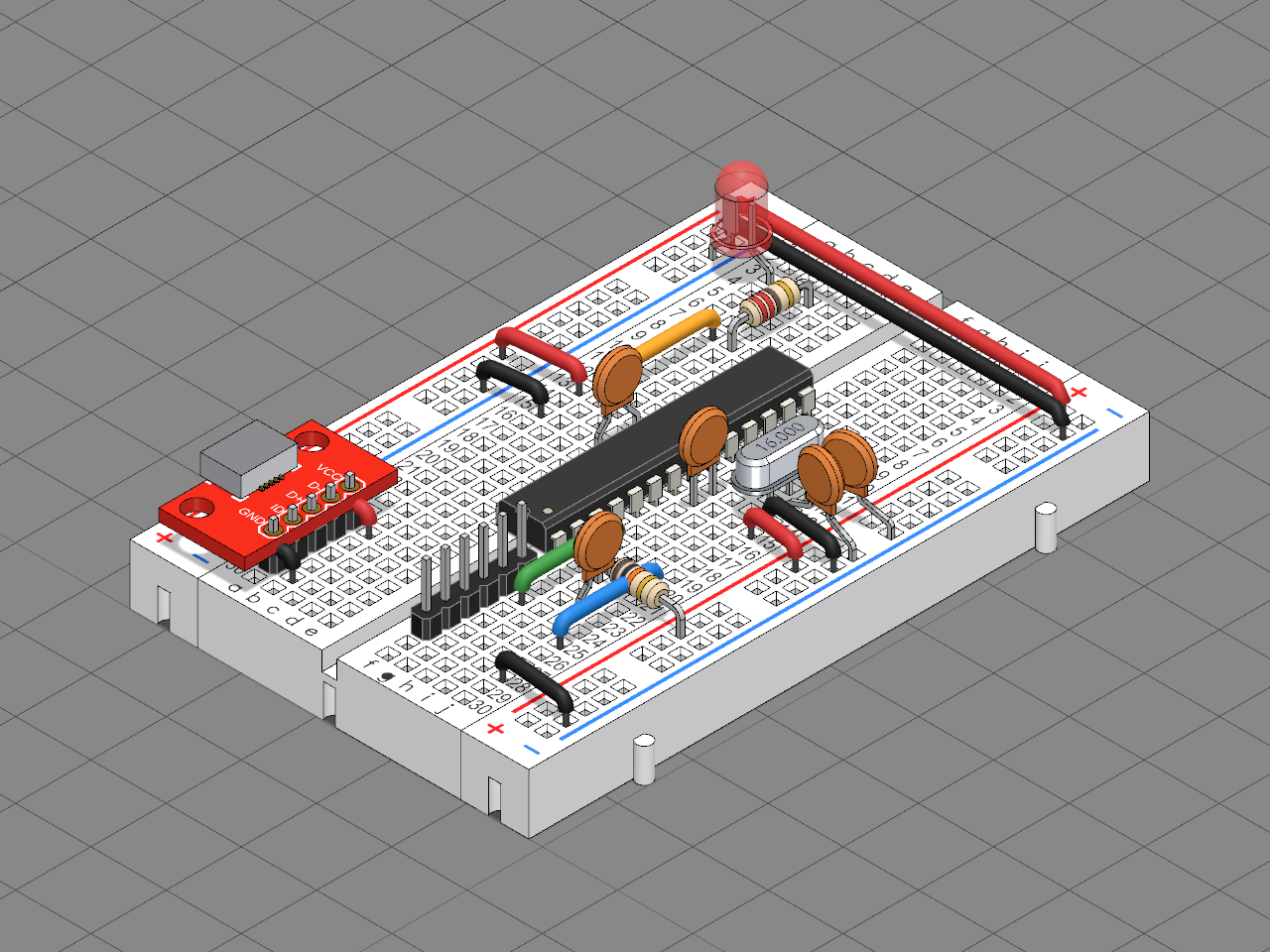
The least an ATmega328P needs to run an Arduino sketch, on a half-size breadboard: the chip, a 16 MHz crystal, a reset pull-up, decoupling capacitors, and an LED on D13 to show it is alive. Power comes in at 5 V through a USB micro-B breakout.
## The circuit
- **Power.** The USB breakout stands on a five-pin header and feeds the top rails. Jumpers bridge the top rails to the bottom ones, and carry 5 V (red) and ground (black) to the chip's supply pins.
- **Decoupling.** A 100 nF ceramic capacitor across VCC and GND, and another across AVCC and GND, each as close to its pins as it fits.
- **Clock.** A 16 MHz crystal in an HC-49/S can on XTAL1 and XTAL2, each side with a 22 pF capacitor to ground.
- **Reset.** A 10 kΩ resistor holds RESET high, so the chip runs.
- **The LED.** D13 runs through a yellow jumper and a 220 Ω resistor to a red LED: the one the Blink example flashes.
- **Programming.** A six-pin FTDI header beside the chip takes a 5 V USB-to-serial adapter: its TX and RX jumpers (blue and green) go to the chip's RXD and TXD, its ground to the − rail, and DTR resets the chip through a 100 nF capacitor, so the Arduino IDE uploads a sketch in place. Its VCC pin is left free: the USB breakout powers the board.
## Build it
1. Seat the chip across the middle gap.
2. Wire the rails and the supply pins, then add both 100 nF capacitors.
3. Add the crystal and its two 22 pF capacitors right beside XTAL1 and XTAL2.
4. Add the reset pull-up, then the LED and its resistor.
5. Add the FTDI header, its three jumpers and the 100 nF capacitor from DTR to RESET.
6. Plug in the USB breakout and a USB-to-serial adapter, choose *Arduino Uno* in the Arduino IDE and upload Blink: the LED blinks. A chip fresh from the factory needs the Arduino bootloader first, burned once from another Arduino as ISP.
Bill of materials
- 1 × Half-Size Breadboard
- 1 × ATmega328P
- 1 × 10 kΩ reset pull-up
- 1 × 100 nF across VCC and GND
- 1 × 100 nF across AVCC and GND
- 1 × 220 Ω for the LED
- 1 × LED on D13
- 1 × Header 1x5 for the USB breakout
- 1 × USB microB breakout, 5 V in
- 1 × 16 MHz crystal on XTAL1 and XTAL2
- 1 × 22 pF from XTAL1 to GND
- 1 × 22 pF from XTAL2 to GND
- 1 × FTDI header: GND, CTS, VCC, TX, RX, DTR
- 1 × 100 nF from DTR to RESET
Licences
- Half-Size Breadboard: CC-BY-4.0, credit Generic. Downloads: STEP, STL and 3MF
- ATmega328P: CC-BY-SA-4.0, credit Microchip. Downloads: STEP, STL and 3MF
- Resistor: CC-BY-SA-4.0, credit ReDo.Pro. Downloads: STEP, STL and 3MF
- Ceramic Capacitor: CC-BY-SA-4.0, credit ReDo.Pro. Downloads: STEP, STL and 3MF
- LED: CC-BY-SA-4.0, credit ReDo.Pro. Downloads: STEP, STL and 3MF
- Header: CC-BY-SA-4.0, credit ReDo.Pro. Downloads: STEP, STL and 3MF
- SparkFun Breakout Board for USB microB: CC-BY-SA-4.0, credit SparkFun. Downloads: STEP, STL and 3MF
- Crystal: CC-BY-SA-4.0, credit ReDo.Pro. Downloads: STEP, STL and 3MF