Micro Gearmotors Soldered to a Motor Driver
by ReDo.Pro (@ReDo.Pro)
Description
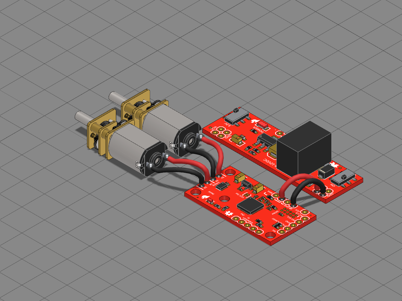
Two Pololu micro metal gearmotors driven by SparkFun's Serial Controlled Motor Driver, powered from a SparkFun Breadboard Power Supply Stick. Nothing plugs in: every wire is soldered at both ends, to a motor's tab and straight into the driver's bare holes, with no header or screw terminal between them.
## How it is wired
- **The motors.** Each gearmotor has two solder tabs at its back. Motor A's go to the driver's AOUT1 and AOUT2 holes, Motor B's to BOUT1 and BOUT2, in 22 AWG wire: red to OUT1, black to OUT2. Swapping a motor's two wires turns it the other way.
- **The power.** The supply stick, switched to 5 V, feeds the driver's VIN and GND holes in thicker 20 AWG wire from its own VCC and GND holes. VIN powers the motors, and 5 V suits these 6 V gearmotors.
- **The controller.** The driver takes its commands over I2C, SPI or serial from a microcontroller wired to its other pins. The controller is left out here; the motor side is the point.
## Build it
1. Strip about 3 mm off each end of six wires: four 22 AWG for the motors, two 20 AWG for the power.
2. Tin each motor tab and solder a wire to it.
3. Push the other end of each motor wire into its hole on the driver and solder it: Motor A to AOUT1 and AOUT2, Motor B to BOUT1 and BOUT2.
4. Solder the power wires into the supply stick's VCC and GND holes, and their other ends into the driver's VIN and GND.
5. Switch the stick to 5 V, wire a microcontroller to the driver, and plug a wall adapter into the stick to drive the motors.
Select a wire to change its thickness in Parameters or its colour in Material. In Electronics mode, pick the Hookup Wire or the Jumper Cable from the Inventory and click a board's bare hole: the wire's end is soldered there.
Bill of materials
- 1 × Motor driver
- 1 × Motor A
- 1 × Motor B
- 1 × Power supply
Licences
- SparkFun Serial Controlled Motor Driver: CC-BY-SA-4.0, credit SparkFun. Downloads: STEP, STL and 3MF
- Micro Metal Gearmotor (precious-metal brushes): CC-BY-SA-4.0, credit Pololu. Downloads: STEP, STL and 3MF
- SparkFun Breadboard Power Supply Stick 5V/3.3V: CC-BY-SA-4.0, credit SparkFun. Downloads: STEP, STL and 3MF