ROBOTIS OMX-AI Follower Arm
by ReDo.Pro (@ReDo.Pro)
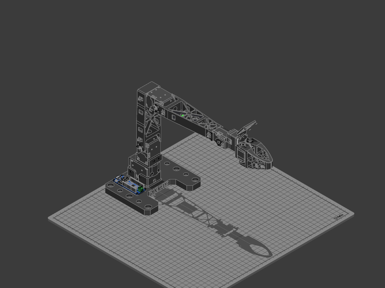
Description
The follower arm of ROBOTIS's OMX-AI: a five-axis arm with a gripper that repeats what a person does with the leader arm, so an AI policy can learn the task from those demonstrations and then run the follower on its own. It reaches 400 mm, weighs 560 g and runs at 12 V. Every part here is ROBOTIS's own, taken from the follower's published drawing and placed where that drawing puts it, but for the 79 screws: those are ReDo's Screw at the size, length and head ROBOTIS use, in the places the drawing puts them. The USB camera the drawing shows above the gripper is bought separately, so it and its four screws are left out.
## How it is built
- **Six DYNAMIXELs.** Three XL430-W250-T are joints 1 to 3. Joint 1 stands in the base without an idler, and joints 2 and 3 carry one, so each link hangs from both sides of its actuator. Three XL330-M288-T are joints 4 and 5 and the gripper. Joint 4 and the gripper carry an idler, and joint 5 has none. Each turns its horn from the Control panel, and its idler with it where it has one. The base plate stands grounded, so each joint turns what hangs off its horn.
- **The controller and power.** An OpenRB-150 screws down beside the base tower and drives all six on one TTL bus. The DC converter under Link-U steps the arm's 12 V down for the three XL330s. The kit's SMPS2DXL, which feeds the bus from the power supply, is not in the drawing.
- **The frames.** The base plate, Frame1, Frame2, Link-L, Link-U, Frame4, the two gripper jaws and the camera frame are 3D printed, and ROBOTIS publish the files to print them. Frame3 is the same part as the leader arm's. A 6704ZZ bearing in Frame1 carries Frame2, so the arm's weight bears on the frame and not on joint 1's horn. Its inner ring turns with Frame2 when joint 1 turns.
- **The gripper.** Gripper L is screwed to the gripper actuator's horn and idler. The gear teeth at its hinge turn Gripper R, which pivots on two idler caps screwed to Frame4, so the two jaws close together. The editor does not join the two jaws' teeth, so turning the gripper's actuator moves Gripper L alone, into Gripper R.
- **The screws.** All 79 are tapping screws that cut their own thread. 59 are M2 pan-head screws: 35 × 6 mm, 8 × 8 mm for the gripper's jaw and 16 × 10 mm into the XL330s' cases and joint 1's horn. 20 are M2.6 binding-head screws: 18 × 8 mm into the XL430s' cases, and 2 × 6 mm through the idler caps.
## Build it
This is ROBOTIS's own assembly order. Set every actuator to its centre position (180°) before you fit it, and keep its horn mark facing up.
1. Fix joint 1 in the base plate's tower with six M2.6 × 8 through its walls, and screw the OpenRB-150 down beside it (M2 × 6). Fit Frame1 over joint 1 (four M2.6 × 8), seat the 6704ZZ bearing in it, and fix Frame2 to joint 1's horn through the bearing (four M2 × 10).
2. Fix joint 2 on top of Frame2 (four M2.6 × 8), and hang Link-L from its horn and idler (M2 × 6).
3. Fix joint 3 to the top of Link-L (four M2.6 × 8), and hang Link-U from its horn and idler (M2 × 6). Screw the DC converter under Link-U (M2 × 6).
4. Fix joint 4 into the end of Link-U (four M2 × 10).
5. Hang Frame3 from joint 4's horn and idler (M2 × 6) and fix joint 5 into it (M2 × 10). Fit Frame4 to joint 5's horn (M2 × 6).
6. Fix the gripper's actuator into Frame4 (M2 × 10) and fit Gripper L to its horn and idler (M2 × 8). Hang Gripper R on its two idler caps, one above and one below, each screwed to Frame4 (M2.6 × 6). Screw the camera frame on top of Frame4 (M2 × 6).
Each actuator needs its own ID on the bus: 11 to 13 for the XL430s up the arm, 14 and 15 for the wrist and 16 for the gripper.
Bill of materials
- 1 × Base Plate
- 1 × OpenRB-150
- 35 × Screw M2 × 6
- 1 × XL430-W250-T, joint 1 (ID 11)
- 18 × Screw M2.6 × 8
- 1 × Frame1
- 1 × 6704ZZ bearing
- 1 × Frame2
- 16 × Screw M2 × 10
- 1 × XL430-W250-T, joint 2 (ID 12)
- 1 × Link-L, upper arm
- 1 × XL430-W250-T, joint 3 (ID 13)
- 1 × Link-U, forearm
- 1 × XL330-M288-T, joint 4 (ID 14)
- 1 × Frame3, wrist
- 1 × XL330-M288-T, joint 5 (ID 15)
- 1 × Frame4, gripper
- 1 × XL330-M288-T, gripper (ID 16)
- 1 × Gripper L
- 1 × Gripper R
- 1 × Idler cap, top
- 1 × Idler cap, bottom
- 8 × Screw M2 × 8
- 2 × Screw M2.6 × 6
- 1 × DC Converter
- 1 × CAMERA Frame
Licences
- OMX-AI Follower Base Plate: LicenseRef-ROBOTIS-CAD, credit ROBOTIS. Downloads: no downloads
- OpenRB-150: LicenseRef-ROBOTIS-CAD, credit ROBOTIS. Downloads: no downloads
- Screw: CC-BY-SA-4.0, credit ReDo.Pro. Downloads: STEP, STL and 3MF
- DYNAMIXEL XL430 / XC430 (no idler): LicenseRef-ROBOTIS-CAD, credit ROBOTIS. Downloads: no downloads
- OMX-AI Follower Frame1: LicenseRef-ROBOTIS-CAD, credit ROBOTIS. Downloads: no downloads
- 6704ZZ Ball Bearing: LicenseRef-ROBOTIS-CAD, credit ROBOTIS. Downloads: no downloads
- OMX-AI Follower Frame2: LicenseRef-ROBOTIS-CAD, credit ROBOTIS. Downloads: no downloads
- DYNAMIXEL XL430 / XC430: LicenseRef-ROBOTIS-CAD, credit ROBOTIS. Downloads: no downloads
- OMX-AI Follower Link-L: LicenseRef-ROBOTIS-CAD, credit ROBOTIS. Downloads: no downloads
- OMX-AI Follower Link-U: LicenseRef-ROBOTIS-CAD, credit ROBOTIS. Downloads: no downloads
- DYNAMIXEL XL330 / XC330: LicenseRef-ROBOTIS-CAD, credit ROBOTIS. Downloads: no downloads
- OMX-AI Frame3: LicenseRef-ROBOTIS-CAD, credit ROBOTIS. Downloads: no downloads
- DYNAMIXEL XL330 / XC330 (no idler): LicenseRef-ROBOTIS-CAD, credit ROBOTIS. Downloads: no downloads
- OMX-AI Follower Frame4: LicenseRef-ROBOTIS-CAD, credit ROBOTIS. Downloads: no downloads
- OMX-AI Follower Gripper L: LicenseRef-ROBOTIS-CAD, credit ROBOTIS. Downloads: no downloads
- OMX-AI Follower Gripper R: LicenseRef-ROBOTIS-CAD, credit ROBOTIS. Downloads: no downloads
- ROBOTIS Idler Cap: LicenseRef-ROBOTIS-CAD, credit ROBOTIS. Downloads: no downloads
- ROBOTIS DC Converter: LicenseRef-ROBOTIS-CAD, credit ROBOTIS. Downloads: no downloads
- OMX-AI Follower CAMERA Frame: LicenseRef-ROBOTIS-CAD, credit ROBOTIS. Downloads: no downloads