Original Prusa MINI+
by ReDo.Toys (@ReDo.Toys)
Description
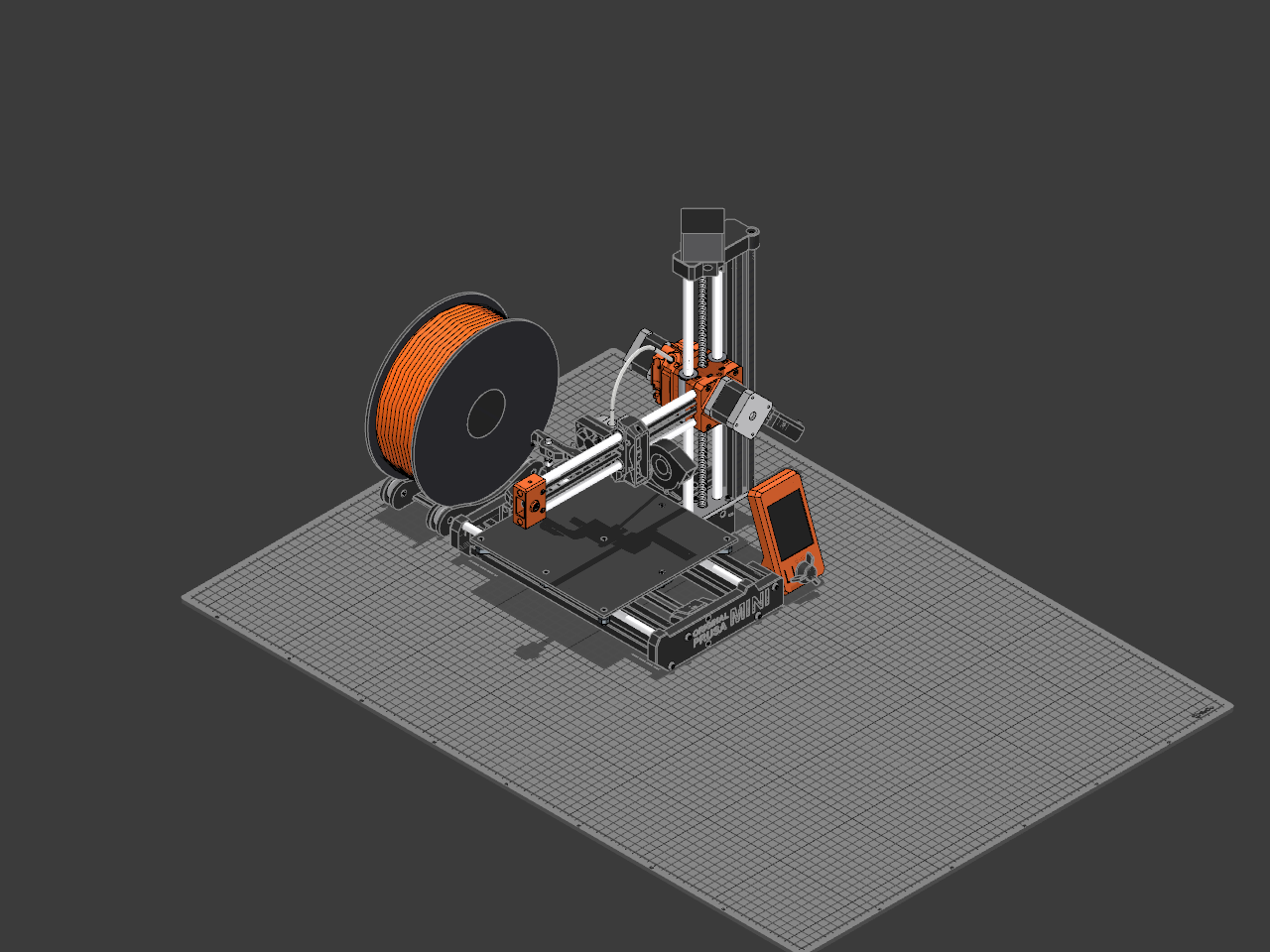
Prusa Research's Original Prusa MINI+ 3D printer, put together from Prusa's own published CAD and drawings, following the order of Prusa's assembly manual. It holds the whole printer: the Y axis with the bed's carriage and its drive, the Z column standing on it, the X axis that rides the column, the extruder, the print head, the heatbed, both belts, the electronics in the base with the display and the power switch, the optional filament sensor and the printed spool holder with a 1 kg spool of PLA on it.
## How it is built
- **The Y frame.** Two 262 mm aluminium extrusions run front to back between the front plate, which carries the Original Prusa MINI logo and is the printer's front foot, and the rear plate. Each end of each extrusion takes two M5×20 button head screws through its plate into the extrusion's tapped corners.
- **The rods and the carriage.** Two 8 mm rods sit in the plates' cradles. The aluminium Y carriage rides them on three LM8UU bearings, two on the left rod and one on the right, the column's side, each held by a steel bearing clip on two M3×10 screws and nyloc nuts. Nine hex spacers stand on the carriage for the heatbed, each on an M3×8 screw from below.
- **The belt's ends.** The belt holder screws under the carriage with two M3×12 screws into the carriage's own threads.
- **The idler.** At the front, the Y belt idler holds a 623 bearing on an M3×20 axle with a nyloc nut. Two M3×20 screws pull it towards the front plate through two square nuts, which is how the belt is tensioned.
- **The drive.** At the rear, the Y motor bolts into the rear plate's holder with three M3×12 screws, with a 16-tooth GT2 pulley on its shaft.
- **The Z base.** The printed Z bottom, the box that will hold the electronics, stands beside the right extrusion, its rear end against the rear plate. A 5 mm steel Z plate bottom lies on top of it and reaches over the extrusion: two M3×20 screws and an M3×12 hold the plate to the box through square nuts, and a second M3×12 goes through the plate into an extrusion nut in the extrusion's top groove. An M3×40 and an M3×20 go through the box's side into two more extrusion nuts in the extrusion's side groove.
- **The Z column.** The 289 mm Z extrusion stands on the plate, held by two M5×20 screws from below whose heads sit in the box's round groove. Two 10 mm rods stand in the box beside it, each clamped by two M3×20 screws into square nuts, with an LM10LUU bearing on each.
- **The Z top.** The printed Z top caps the column and the rods with two M5×16 screws into the extrusion. The Z motor stands on it, held by two M3×12 screws from below, its lead screw running down between the rods to the plate.
- **The Z carriage.** The printed Z carriage front and rear close round both LM10LUU bearings with four M3×30 screws into square nuts. The black trapezoidal nut on the lead screw is screwed under it with two M3×20 screws, so turning the screw lifts the carriage.
- **The X axis.** Two 8 mm X rods reach out over the bed from the carriage front, each clamped by two M3×12 screws. The X end caps their far ends, with a 623 bearing on an M3×20 axle as the belt's idler and two M3×12 screws that set the belt's tension. The X carriage rides the rods on two LM8UU bearings. The X motor bolts to the front of the Z carriage with two M3×12 screws, its 16-tooth GT2 pulley inside the carriage between the rods.
- **The extruder.** Behind the Z carriage, the orange extruder front and rear close round the steel filament drive gear, which turns in a 625 bearing in each half and is driven by a pinion on the extruder motor. The motor bolts to the front half with two M3×12 screws, and three M3×25 screws hold the halves together through nuts in the front. The sprung idler swings on an M3×25 screw and a nyloc nut; its own 625 bearing on a 5 mm shaft presses the filament against the gear, held there by an M3×40 screw and a 5×15 spring into a square nut in the idler. Two more M3×25 screws carry the extruder on the Z carriage, the upper one also the hinge of the small inspection door.
- **The print head.** The hotend, Prusa's heatsink with the heatbreak, heater block and nozzle, screws to the X carriage's side with two M3×20 screws. The fan spacer and the 40 mm hotend fan sit on the heatsink's face, held by one M3×20 into the heatsink; the SuperPINDA holder hangs from the fan's lower corner on a second M3×20, with an M3×12 and a nyloc nut, and grips the SuperPINDA probe with an M3×12. The cable clip slides on the spacer's teeth on an M3×20. The 5015 print fan screws to the carriage's other side with an M3×20. The PTFE tube runs from the top of the heatsink up and over to the extruder.
- **The heatbed.** The heatbed lies on the nine spacers, held by nine M3×4 countersunk screws. Its power cable is screwed to the two terminals in its tab with M3×8 screws and nyloc nuts, and the two cable covers close round them with an M3×12 into a nyloc nut in the bottom cover.
- **The belts.** The 6 mm GT2 Y belt runs from the belt holder's lower groove round the front idler's 623 bearing, round the Y motor's pulley and back into the holder's upper groove. The X belt runs from the X carriage's upper groove round the X end's 623 bearing, round the X motor's pulley and back into the carriage's lower groove.
- **The electronics.** The Buddy board lies in the Z bottom on four M3×6 screws. The snap-in power switch sits in the square hole in the base's side, wired to the board's two power pins.
- **The display.** The colour display and its encoder sit in the orange display box, its knob on the encoder's shaft. The box hangs under the front plate on one M3×20 screw, and tilts on it.
- **The cover.** The Z bottom cover hooks its teeth into the base's grooves over the board, and the small cable cover closes it with an M3×12 screw into a square nut in the base.
- **The filament sensor.** A 7 mm steel ball rests in the sensor box's pocket against the filament, under the lever, which swings on an M3×12 screw. A 10×6×2 magnet in the lever and another in the box repel, pressing the lever onto the ball; when filament runs out the ball drops and the lever's flag leaves the IR sensor's fork. The IR sensor board stands against the box's back wall, the cover closes the box with two M3×12 screws, and the box slides onto a 150 mm PTFE tube into the extruder's inlet, clamped by the last M3×12. A 15 mm PTFE stub lines the box's other end.
- **The spool holder.** Two pairs of printed feet, each pair closed round two 608 bearings with M3×12 screws and nuts, slide along two dovetail rails and are locked to them by four M3×8 screws. It stands apart, behind the printer, with a 1 kg spool of 1.75 mm PLA resting on its bearings, each flange against the inner feet's guide.
## Build it
1. Fit the three bearings into the Y carriage, each under its clip with two M3×10 screws and nyloc nuts.
2. Screw the nine heatbed spacers onto the carriage with M3×8 screws from below, and screw the belt holder under it with two M3×12 screws.
3. Screw the front plate to the front ends of both extrusions, two M5×20 screws each.
4. Push a square nut into each of the idler's two slots, fit the 623 bearing on its M3×20 axle and nyloc nut, and hang the idler on the front plate with two M3×20 screws, left 1 to 2 mm loose.
5. Slide the rods through the carriage's bearings and into the front plate.
6. Fit the pulley on the Y motor's shaft, 2 mm off the motor, and screw the motor into the rear plate with three M3×12 screws.
7. Slide three extrusion nuts into the right extrusion: two into its outer side groove, one into its top groove. Later they cannot go in.
8. Push the rear plate onto the rods and the extrusions and screw it on, two M5×20 screws each.
9. Push the square nuts into the Z bottom: three under the plate's screws and four at the rod clamps.
10. Screw the Z plate bottom to the foot of the Z extrusion with two M5×20 screws, stand it on the Z bottom with the screw heads in the round groove, and screw it down with two M3×20 screws and an M3×12.
11. Set the Z bottom against the right extrusion, its rear end on the rear plate, and join them: the M3×40 and M3×20 through the box into the side groove's nuts, and an M3×12 through the plate into the top groove's nut.
12. Push both Z rods into the Z bottom and clamp them with four M3×20 screws, and slide an LM10LUU bearing onto each.
13. Screw the Z motor onto the Z top with two M3×12 screws and run the trapezoidal nut onto its screw.
14. Lower the Z top onto the rods and the extrusion, the lead screw into the plate's middle hole, and screw it down with two M5×16 screws.
15. Push both X rods into the Z carriage front and clamp them with four M3×12 screws into square nuts.
16. Fit the 623 bearing in the X end on its M3×20 axle and nyloc nut, push the X end onto the rods' far ends and set its two M3×12 screws half in.
17. Push the X carriage onto two LM8UU bearings on the rods.
18. Fit the pulley on the X motor's shaft, 1 mm off the motor, and screw the motor to the Z carriage front with two M3×12 screws.
19. Close the Z carriage rear over the LM10LUU bearings with four M3×30 screws, and screw the trapezoidal nut under the carriage with two M3×20 screws.
20. Fit the pinion on the extruder motor's shaft, 1.5 mm off the motor, its set screw on the shaft's flat.
21. Push three nuts and a 625 bearing into the extruder front, and a nut, a nyloc nut and a 625 bearing into the extruder rear.
22. Push the square nut into the idler, and its 625 bearing on the 5×12 shaft.
23. Screw the extruder front onto the motor with two M3×12 screws, and drop the drive gear into its bearing, the long grooved end up.
24. Close the rear over it with three M3×25 screws.
25. Hang the idler on its M3×25 screw, not tight, and pull it in with the M3×40 screw through the 5×15 spring until the screw's head is level with the plastic. Fit the PTFE tube's screw and nut, M3×12.
26. Hold the extruder against the Z carriage's rear, the brass fitting top right, and screw it on with an M3×25 in the lower hole; set the inspection door on top and screw it on with the last M3×25, loose enough to swing.
27. Hold the hotend against the X carriage and screw it on with two M3×20 screws, the upper one first.
28. Set the print fan against the carriage's other side and screw it on with an M3×20.
29. Put the 40 mm fan on the fan spacer, its sticker towards the heatsink and its cable to the upper left, and screw both to the heatsink with an M3×20 in the upper left hole.
30. Push a nyloc nut into the SuperPINDA holder, set the holder on the fan, and screw it on with an M3×12 and an M3×20.
31. Start the M3×12 into the holder's clamp, push the SuperPINDA in until 4 to 5 threads show below the holder, and tighten it gently.
32. Gather the hotend's cables into the fan spacer clip and screw the clip to the spacer with an M3×20, then back it off a quarter turn so the clip moves freely.
33. Push one end of the 275 mm PTFE tube into the extruder's brass fitting and tighten the nut, then the other end into the print head the same way.
34. Put two M3×8 screws through the heatbed's terminals from the top, fit the cable's lugs from below and tighten them with nyloc nuts.
35. Put a nyloc nut into the bottom cable cover, close the two covers round the terminals and screw them together with an M3×12.
36. Lay the heatbed on the nine spacers and screw it down with nine M3×4 countersunk screws: the centre one, then the four at the edges, then the four corners.
37. Run the Y belt from the holder's lower groove round the idler and the Y motor's pulley and back into the upper groove, then tension it with the idler's two screws.
38. Run the X belt from the X carriage's upper groove round the X end's bearing and the X motor's pulley and back into the lower groove, then tension it with the X end's two screws.
39. Lay the Buddy board in the Z bottom and screw it down with four M3×6 screws.
40. Fit the display and its encoder into the display box, put the knob on the shaft, and hang the box under the front plate with the M3×20 screw.
41. Push the power switch into the square hole in the Z bottom, the off mark to the right, and plug its two wires onto the board's power pins.
42. Drop the 7 mm steel ball into the sensor box's pocket and the IR sensor board against the back wall, set the lever on its pivot with an M3×12 screw, not tight, and push one magnet into the lever and one into the box so that they repel.
43. Close the sensor with its cover and two M3×12 screws, push the 15 mm PTFE stub into its end, slide the sensor onto the inlet tube in the extruder and clamp it gently with the last M3×12.
44. Push the square nut into the Z bottom, hook the cover's teeth into the base's grooves, set the cable cover on top and screw it down with an M3×12.
45. Close each pair of spool holder feet round two 608 bearings, with an M3×12 screw and nut each way.
46. Slide both rails into the first pair's grooves, flush with its edge, and lock them with two M3×8 screws; slide the second pair on to the spool's width and lock it with the last two.
47. Set the filament spool on the four bearings, each flange against the inner feet.
The steel sheet goes on after the first calibration, as Prusa's guide says. The PTFE tubes are drawn as straight runs and even arcs; the real ones lie more freely. The belts are drawn without their teeth, and the boards and the IR sensor are simplified: their outlines, holes, chips and plugs, not every part on them. The cables, the textile sleeves, the anti-vibration pads and the IR sensor's M2×8 screw are not drawn.
Bill of materials
- 1 × Y plate, front
- 1 × Y plate, rear
- 1 × Y extrusion, right
- 1 × Y extrusion, left
- 1 × M5×20 screw, front plate 1
- 1 × M5×20 screw, rear plate 1
- 1 × M5×20 screw, front plate 2
- 1 × M5×20 screw, rear plate 2
- 1 × M5×20 screw, front plate 3
- 1 × M5×20 screw, rear plate 3
- 1 × M5×20 screw, front plate 4
- 1 × M5×20 screw, rear plate 4
- 1 × Y rod, left
- 1 × Y rod, right
- 1 × Y carriage
- 1 × LM8UU, right
- 1 × Bearing clip, right
- 2 × M3×10 screw, bearing clip right
- 2 × M3 nyloc nut, bearing clip right
- 1 × LM8UU, left front
- 1 × Bearing clip, left front
- 2 × M3×10 screw, bearing clip left front
- 2 × M3 nyloc nut, bearing clip left front
- 1 × LM8UU, left rear
- 1 × Bearing clip, left rear
- 2 × M3×10 screw, bearing clip left rear
- 2 × M3 nyloc nut, bearing clip left rear
- 1 × Heatbed spacer 1
- 1 × M3×8 screw, heatbed spacer 1
- 1 × Heatbed spacer 2
- 1 × M3×8 screw, heatbed spacer 2
- 1 × Heatbed spacer 3
- 1 × M3×8 screw, heatbed spacer 3
- 1 × Heatbed spacer 4
- 1 × M3×8 screw, heatbed spacer 4
- 1 × Heatbed spacer 5
- 1 × M3×8 screw, heatbed spacer 5
- 1 × Heatbed spacer 6
- 1 × M3×8 screw, heatbed spacer 6
- 1 × Heatbed spacer 7
- 1 × M3×8 screw, heatbed spacer 7
- 1 × Heatbed spacer 8
- 1 × M3×8 screw, heatbed spacer 8
- 1 × Heatbed spacer 9
- 1 × M3×8 screw, heatbed spacer 9
- 1 × Y belt holder
- 2 × M3×12 screw, belt holder
- 1 × Y belt idler
- 2 × M3×20 screw, belt tension
- 2 × M3 square nut, belt idler
- 1 × M3×20 screw, idler axle
- 1 × M3 nyloc nut, idler axle
- 1 × 623ZZ bearing, idler pulley
- 1 × Y motor
- 3 × M3×12 screw, Y motor
- 1 × GT2 pulley 16T, Y motor
- 1 × Z bottom
- 1 × Z plate bottom
- 1 × Z extrusion
- 1 × M5×20 screw, Z plate bottom 1
- 1 × M5×16 screw, Z top 1
- 1 × M5×20 screw, Z plate bottom 2
- 1 × M5×16 screw, Z top 2
- 2 × M3×20 screw, Z plate bottom
- 3 × M3 square nut, Z bottom
- 1 × M3×12 screw, Z plate bottom
- 1 × M3×12 screw, Z plate to Y extrusion
- 1 × M3nE extrusion nut, top groove
- 1 × M3×20 screw, Z bottom to Y extrusion
- 2 × M3nE extrusion nut, side groove
- 1 × M3×40 screw, Z bottom to Y extrusion
- 1 × Z rod, left
- 1 × Z rod, right
- 4 × M3×20 screw, Z rod clamp
- 4 × M3 square nut, Z rod clamp
- 1 × Z top
- 1 × Z motor
- 2 × M3×12 screw, Z motor
- 1 × Z carriage, front
- 1 × Z carriage, rear
- 1 × LM10LUU, left
- 1 × LM10LUU, right
- 4 × M3×30 screw, Z carriage
- 4 × M3 square nut, Z carriage
- 1 × Trapezoidal nut, Z
- 2 × M3×20 screw, trapezoidal nut
- 2 × M3 square nut, trapezoidal nut
- 1 × X rod, top
- 1 × X rod, bottom
- 4 × M3×12 screw, X rod clamp
- 4 × M3 square nut, X rod clamp
- 1 × X motor
- 2 × M3×12 screw, X motor
- 1 × GT2 pulley 16T, X motor
- 1 × X end
- 2 × M3×12 screw, X end
- 1 × M3×20 screw, X idler axle
- 1 × M3 nyloc nut, X idler axle
- 1 × 623ZZ bearing, X idler pulley
- 1 × X carriage
- 1 × LM8UU, X top
- 1 × LM8UU, X bottom
- 1 × Extruder front
- 1 × Extruder rear
- 1 × Extruder motor
- 1 × Extruder motor pinion
- 1 × Filament drive gear
- 1 × 625 2Z bearing, extruder front
- 1 × 625 2Z bearing, extruder rear
- 2 × M3×12 screw, extruder motor
- 3 × M3×25 screw, extruder halves
- 3 × M3 nut, extruder front
- 1 × M3×25 screw, extruder to Z carriage
- 1 × M3×25 screw, inspection door
- 1 × Extruder inspection door
- 1 × Extruder idler
- 1 × 625 2Z bearing, extruder idler
- 1 × 5×12 shaft, extruder idler
- 1 × M3×25 screw, idler pivot
- 1 × M3 nyloc nut, idler pivot
- 1 × M3×40 screw, idler spring
- 1 × 5×15 spring, extruder idler
- 1 × M3 square nut, extruder idler
- 1 × M3×12 screw, PTFE tube
- 1 × M3 nut, PTFE tube
- 1 × Heatsink
- 1 × Heatbreak
- 1 × Heater block
- 1 × Nozzle
- 2 × M3×20 screw, hotend
- 1 × Fan spacer
- 1 × Hotend fan
- 1 × M3×20 screw, hotend fan
- 1 × Print fan
- 1 × M3×20 screw, print fan
- 1 × SuperPINDA holder
- 1 × M3×20 screw, SuperPINDA holder
- 1 × M3×12 screw, SuperPINDA holder
- 1 × M3 nyloc nut, SuperPINDA holder
- 1 × SuperPINDA
- 1 × M3×12 screw, SuperPINDA clamp
- 1 × Fan spacer clip
- 1 × M3×20 screw, fan spacer clip
- 1 × PTFE tube, print head
- 1 × Heatbed
- 1 × M3×4 countersunk screw, heatbed 1
- 1 × M3×4 countersunk screw, heatbed 2
- 1 × M3×4 countersunk screw, heatbed 3
- 1 × M3×4 countersunk screw, heatbed 4
- 1 × M3×4 countersunk screw, heatbed 5
- 1 × M3×4 countersunk screw, heatbed 6
- 1 × M3×4 countersunk screw, heatbed 7
- 1 × M3×4 countersunk screw, heatbed 8
- 1 × M3×4 countersunk screw, heatbed 9
- 2 × M3×8 screw, heatbed terminal
- 2 × M3 nyloc nut, heatbed terminal
- 1 × Heatbed cable cover, bottom
- 1 × Heatbed cable cover, top
- 1 × M3×12 screw, heatbed cable cover
- 1 × M3 nyloc nut, heatbed cable cover
- 1 × Display box
- 1 × Display
- 1 × Display knob
- 1 × M3×20 screw, LCD
- 1 × Buddy board
- 4 × M3×6 screw, Buddy board
- 1 × Power switch
- 1 × M3 square nut, electronics cover
- 1 × Electronics cover
- 1 × Electronics cable cover
- 1 × M3×12 screw, electronics cover
- 1 × PTFE tube, filament inlet
- 1 × Filament sensor box
- 1 × Filament sensor cover
- 1 × Filament sensor lever
- 1 × Filament sensor board
- 1 × Steel ball, filament sensor
- 1 × Magnet, filament sensor box
- 1 × Magnet, filament sensor lever
- 1 × PTFE tube, filament sensor
- 1 × M3×12 screw, filament sensor lever
- 2 × M3×12 screw, filament sensor cover
- 1 × M3×12 screw, filament sensor PTFE tube
- 1 × Spool holder base, front outer
- 1 × Spool holder base, front inner
- 2 × 608ZZ bearing, spool holder front
- 4 × M3×12 screw, spool holder base
- 4 × M3 nut, spool holder base
- 4 × M3×8 screw, spool holder rail
- 1 × Spool holder base, rear outer
- 1 × Spool holder base, rear inner
- 2 × 608ZZ bearing, spool holder rear
- 1 × Spool holder rail, left
- 1 × Spool holder rail, right
- 1 × Filament spool
- 1 × GT2 belt, Y axis
- 1 × GT2 belt, X axis
Licences
- Prusa MINI Y Plate Front: GPL 3.0 or later, credit Prusa Research. Downloads: STEP, STL and 3MF
- Prusa MINI Y Plate Rear: GPL 3.0 or later, credit Prusa Research. Downloads: STEP, STL and 3MF
- Prusa MINI Extrusion: CC BY-SA 4.0, credit ReDo.Pro. Downloads: STEP, STL and 3MF
- Screw: CC BY-SA 4.0, credit ReDo.Pro. Downloads: STEP, STL and 3MF
- Rod: CC BY-SA 4.0, credit ReDo.Pro. Downloads: STEP, STL and 3MF
- Prusa MINI Y Carriage: GPL 3.0 or later, credit Prusa Research. Downloads: STEP, STL and 3MF
- LM8UU Linear Bearing: CC BY 3.0, credit FreeCAD Library. Downloads: STEP, STL and 3MF
- Prusa MINI Bearing Clip: GPL 3.0 or later, credit Prusa Research. Downloads: STEP, STL and 3MF
- Nut: CC BY-SA 4.0, credit ReDo.Pro. Downloads: STEP, STL and 3MF
- Hex Spacer: CC BY-SA 4.0, credit ReDo.Pro. Downloads: STEP, STL and 3MF
- Prusa MINI Y Belt Holder: GPL 3.0 or later, credit Prusa Research. Downloads: STEP, STL and 3MF
- Prusa MINI Y Idler: GPL 3.0 or later, credit Prusa Research. Downloads: STEP, STL and 3MF
- 623ZZ Ball Bearing: CC BY 3.0, credit FreeCAD Library. Downloads: STEP, STL and 3MF
- NEMA 17 Stepper Motor (40 mm): CC BY 3.0, credit FreeCAD Library. Downloads: STEP, STL and 3MF
- GT2 Timing Pulley: CC BY-SA 4.0, credit ReDo.Pro. Downloads: STEP, STL and 3MF
- Prusa MINI Z Bottom: GPL 3.0 or later, credit Prusa Research. Downloads: STEP, STL and 3MF
- Prusa MINI Z Bottom Plate: GPL 3.0 or later, credit Prusa Research. Downloads: STEP, STL and 3MF
- Prusa MINI Extrusion Nut: CC BY-SA 4.0, credit ReDo.Pro. Downloads: STEP, STL and 3MF
- Prusa MINI Z Top: GPL 3.0 or later, credit Prusa Research. Downloads: STEP, STL and 3MF
- Prusa MINI Z Motor: CC BY-SA 4.0, credit ReDo.Pro. Downloads: STEP, STL and 3MF
- Prusa MINI Z Carriage Front: GPL 3.0 or later, credit Prusa Research. Downloads: STEP, STL and 3MF
- Prusa MINI Z Carriage Rear: GPL 3.0 or later, credit Prusa Research. Downloads: STEP, STL and 3MF
- Linear Bearing (Parametric): CC BY-SA 4.0, credit ReDo.Pro. Downloads: STEP, STL and 3MF
- Prusa MINI Z Nut: CC BY-SA 4.0, credit ReDo.Pro. Downloads: STEP, STL and 3MF
- Prusa MINI X End: GPL 3.0 or later, credit Prusa Research. Downloads: STEP, STL and 3MF
- Prusa MINI X Carriage: GPL 3.0 or later, credit Prusa Research. Downloads: STEP, STL and 3MF
- Prusa MINI Extruder Front: GPL 3.0 or later, credit Prusa Research. Downloads: STEP, STL and 3MF
- Prusa MINI Extruder Rear: GPL 3.0 or later, credit Prusa Research. Downloads: STEP, STL and 3MF
- Prusa MINI Extruder Motor Pinion: GPL 3.0 or later, credit Prusa Research. Downloads: STEP, STL and 3MF
- Prusa MINI Filament Drive Gear: GPL 3.0 or later, credit Prusa Research. Downloads: STEP, STL and 3MF
- Ball Bearing (Parametric): CC BY-SA 4.0, credit ReDo.Pro. Downloads: STEP, STL and 3MF
- Prusa MINI Extruder Inspection Door: GPL 3.0 or later, credit Prusa Research. Downloads: STEP, STL and 3MF
- Prusa MINI Extruder Idler: GPL 3.0 or later, credit Prusa Research. Downloads: STEP, STL and 3MF
- Compression Spring: CC BY-SA 4.0, credit ReDo.Pro. Downloads: STEP, STL and 3MF
- Prusa MINI Hotend Heatsink: GPL 3.0 or later, credit Prusa Research. Downloads: STEP, STL and 3MF
- Prusa MINI Heatbreak: CC BY-SA 4.0, credit ReDo.Pro. Downloads: STEP, STL and 3MF
- Prusa MINI Heater Block: CC BY-SA 4.0, credit ReDo.Pro. Downloads: STEP, STL and 3MF
- Prusa MINI Nozzle 0.4: CC BY-SA 4.0, credit ReDo.Pro. Downloads: STEP, STL and 3MF
- Prusa MINI Fan Spacer: GPL 3.0 or later, credit Prusa Research. Downloads: STEP, STL and 3MF
- Axial Fan: CC BY-SA 4.0, credit ReDo.Pro. Downloads: STEP, STL and 3MF
- Blower Fan 5015: CC BY-SA 4.0, credit ReDo.Pro. Downloads: STEP, STL and 3MF
- Prusa MINI SuperPINDA Holder: GPL 3.0 or later, credit Prusa Research. Downloads: STEP, STL and 3MF
- Prusa SuperPINDA: CC BY-SA 4.0, credit ReDo.Pro. Downloads: STEP, STL and 3MF
- Prusa MINI Fan Spacer Clip: GPL 3.0 or later, credit Prusa Research. Downloads: STEP, STL and 3MF
- PTFE Tube: CC BY-SA 4.0, credit ReDo.Pro. Downloads: STEP, STL and 3MF
- Prusa MINI Heatbed: CC BY-SA 4.0, credit ReDo.Pro. Downloads: STEP, STL and 3MF
- Prusa MINI Heatbed Cable Cover Bottom: GPL 3.0 or later, credit Prusa Research. Downloads: STEP, STL and 3MF
- Prusa MINI Heatbed Cable Cover Top: GPL 3.0 or later, credit Prusa Research. Downloads: STEP, STL and 3MF
- Prusa MINI Display Box: GPL 3.0 or later, credit Prusa Research. Downloads: STEP, STL and 3MF
- Prusa MINI Display: CC BY-SA 4.0, credit ReDo.Pro. Downloads: STEP, STL and 3MF
- Prusa MINI Display Knob: GPL 3.0 or later, credit Prusa Research. Downloads: STEP, STL and 3MF
- Prusa MINI Buddy Board: CC BY-SA 4.0, credit ReDo.Pro. Downloads: STEP, STL and 3MF
- Rocker Switch, Snap-in: CC BY-SA 4.0, credit ReDo.Pro. Downloads: STEP, STL and 3MF
- Prusa MINI Z Bottom Cover: GPL 3.0 or later, credit Prusa Research. Downloads: STEP, STL and 3MF
- Prusa MINI Z Bottom Cable Cover: GPL 3.0 or later, credit Prusa Research. Downloads: STEP, STL and 3MF
- Prusa MINI Filament Sensor Box: GPL 3.0 or later, credit Prusa Research. Downloads: STEP, STL and 3MF
- Prusa MINI Filament Sensor Cover: GPL 3.0 or later, credit Prusa Research. Downloads: STEP, STL and 3MF
- Prusa MINI Filament Sensor Lever: GPL 3.0 or later, credit Prusa Research. Downloads: STEP, STL and 3MF
- Prusa MINI Filament Sensor Board: CC BY-SA 4.0, credit ReDo.Pro. Downloads: STEP, STL and 3MF
- Steel Ball: CC BY-SA 4.0, credit ReDo.Pro. Downloads: STEP, STL and 3MF
- Block Magnet: CC BY-SA 4.0, credit ReDo.Pro. Downloads: STEP, STL and 3MF
- Prusa MINI Spool Holder Base: GPL 3.0 or later, credit Prusa Research. Downloads: STEP, STL and 3MF
- 608ZZ Ball Bearing: CC BY 3.0, credit FreeCAD Library. Downloads: STEP, STL and 3MF
- Prusa MINI Spool Holder Rail: GPL 3.0 or later, credit Prusa Research. Downloads: STEP, STL and 3MF
- 3D Printer Filament: CC BY-SA 4.0, credit ReDo.Pro. Downloads: STEP, STL and 3MF
- GT2 Belt: CC BY-SA 4.0, credit ReDo.Pro. Downloads: STEP, STL and 3MF